Analysis and Design of Steel Roof Trusses
TweetThe use of trusses is that the most widespread alternative for roof construction in Nigeria. the first choice of fabric for it's timber and steel.
The best part about truss roof is that by using the truss web the ducts and pipes that are needed to be installed are often done so by using it. albeit , it's important to pay careful attention to the planning of the truss member and their connections and failure in building a correct one can cause the loss of life and also economy.
On the 10th of December, 2016 the roof of a church in Uyo, AkwaIbom State, Nigeria collapsed leaving 60 worshippers dead and lots of injured. Its incident shows how important it's for engineers to pay careful attention to the planning situations.
A system of triangulated members that are connected and designed to hold load is named a truss. Inherently, a truss is stable in its shape and may resist load by developing primary axial forces which in nature are often tensile or compressive.
It is always assumed that the connections of trusses are nominally pinned as a really stiff connection in truss can cause secondary effects like bending moments and shear force which are induced within the truss members.
The ratio of span to truss depth should be within a variety of 10 to fifteen for an honest structural performance of roof trusses. albeit , it must be considered that the architectural design of the building ultimately determines the already existing geometry which is what governs the slope that's given to the highest chord of the truss.
A number of buckling models are to be considered for the designing of a compression member during a roof truss.
In most truss members only the evaluation of the flexural buckling of the compressed members within the plane of the truss structure and out of the plane of the truss structure must be calculated. In Eurocode3 the flexural buckling is achieved by the appliance of a discount factor to the compression resistance.
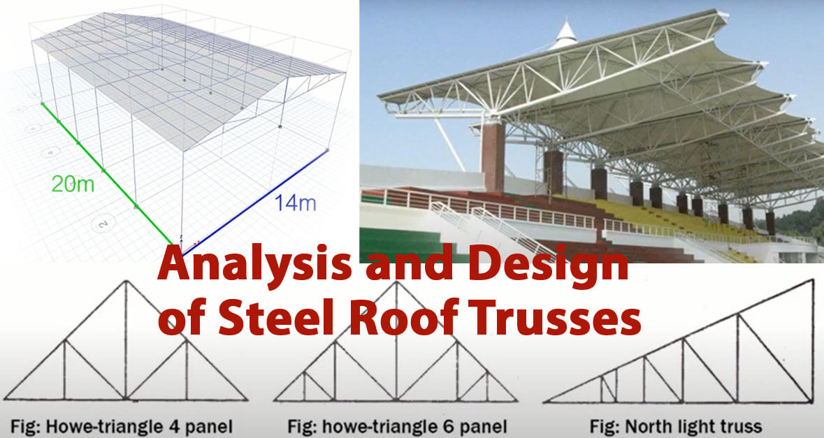
Design example of simple truss roof
Measurements of the simple skeletal structure of the roof system: 18.0 m long, 7.2 m wide
Truss configuration spaced at 3m intervals
Steel grade S 275
Load analysis:
Span of the roof truss: 7.2m
Truss spacing: 3.0m
Nodal spacing that is present in the truss: 1.2 m
Permanent dead loads
Long span aluminum roof sheet self-weight (gauge thickness- 0.55mm): 0.019 kN/m2
Weight of ceiling (10mm insulation fibre board): 0.077kN/m2
The weight of services: 0.1 kN/m2
Weight of purlin (assuming CH 150X75X18 kg/m)= (18X3m)/ (1.2X3)= 15 kg/m2= 0.147 kN/m2
Self-weight of trusses (assuming)= 0.2 kN/m2
Total dead load (gk)= 0.536kN/m2
Thereby, the total nodal permanent load (gk)= 0.536 kN/m2 X 1.2m X 3m= 1.9296 kN
Variable Imposed load
Category of the roof = Category H- Roof which is not accessible for final maintenance and repair Imposed load on roof (qk)= 0.75 kN/m2
Thereby, the nodal variable load is (Qk)= 0.75kN/m2 X 1.2m X 3m= 2.7 kN